Equipment status at a glance by color — ISO-standard vibration monitoring
Measures and displays 3-axis vibration in real time and instantly signals good/caution/danger by color using international standard (ISO 10816/20816) zones (A·B·C·D).
How this HMI works
It shows the 3-axis (X/Y/Z) velocity RMS, acceleration spectrum, and trends of motors, pumps, and fans on a single screen. FFT and spectrum computation is built into the sensor so the HMI displays with low latency, and connecting the vibration sensor over RS-485/RS-232 lets it work without additional equipment.
Key features
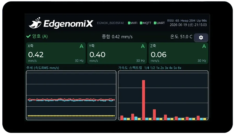
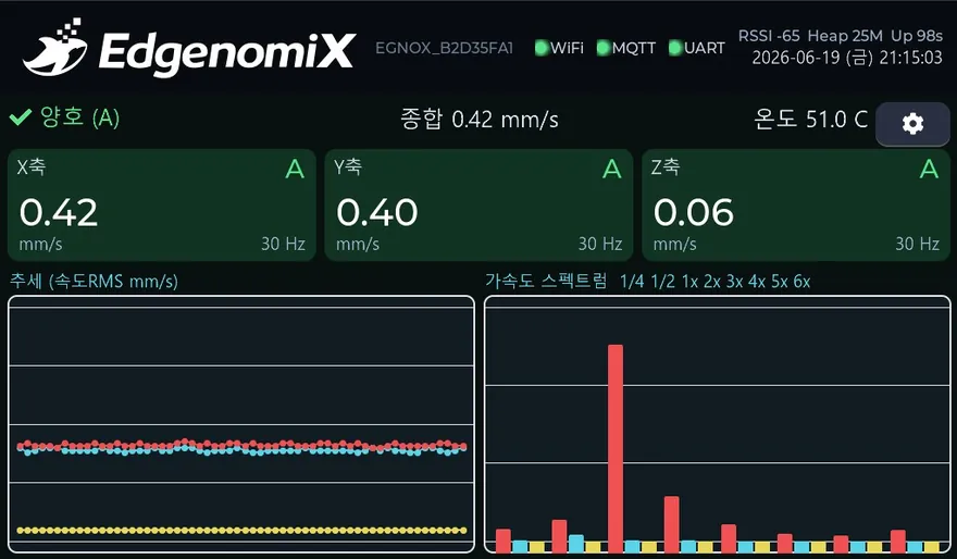
3-axis vibration card
Displays per-axis velocity RMS (mm/s), frequency, and standard zone colors.
Acceleration spectrum
Identifies imbalance, misalignment, and bearing fault patterns via 1×–6× harmonic bars.
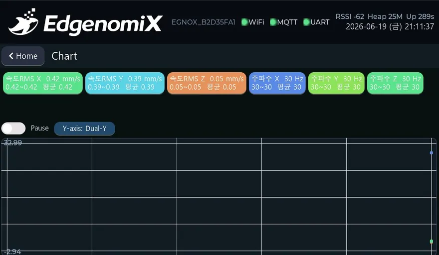
Trend graph
Tracks changes over time with auto-scaling, down to fine fluctuations.
Standard-based alarms
Provides ISO vibration zone (A/B/C/D) colors and threshold alerts.
Sensor-embedded FFT/DSP
The sensor handles heavy computation while the HMI displays it instantly.
Cloud integration
Sends measurements over MQTT to link with remote history and extended analytics.
Browse screens
These are actual screens designed and built in-house by EdgenomiX.
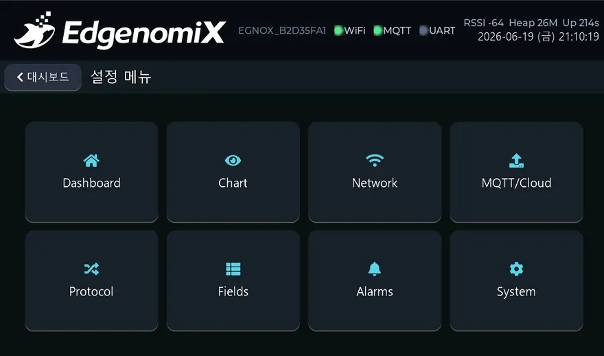
* These are actual built screens; the configuration may vary depending on the deployment environment.
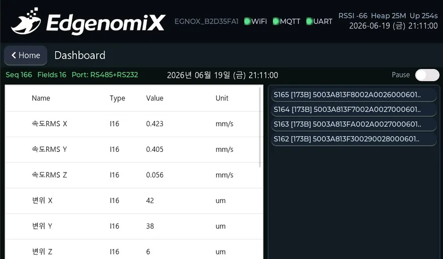
Items viewed and controlled on screen
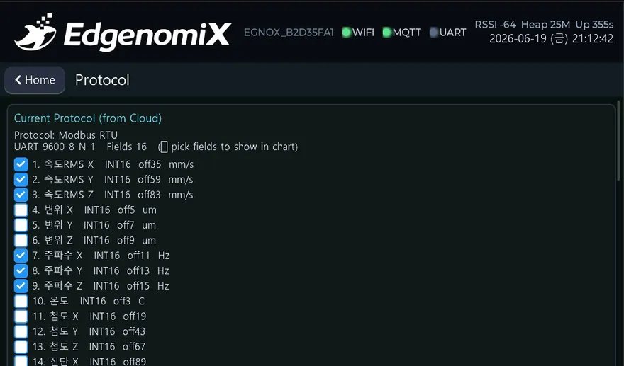
How it connects to equipment
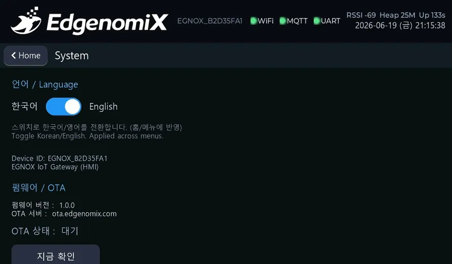
All EGNOX custom HMIs commonly support Wi-Fi/Ethernet networking, OTA over-the-air firmware updates (signature verification and rollback), remote screen viewing via web browser, and multilingual (Korean/English) operation. The communication register map is mapped during the screen design stage to match the equipment model.
Where it is applied
Common HMI hardware platform
| Display | 7″ IPS 1024×600 · capacitive multi-touch |
|---|---|
| Processor | ESP32-P4 dual-core RISC-V + ESP32-C6 wireless |
| Memory | 32MB PSRAM · 16MB Flash |
| Serial | RS-485 · RS-232 |
| Network | Wi-Fi (2.4GHz) · Ethernet (100M) |
| Remote | OTA firmware updates (signature verification and rollback) · web remote screen viewing |
| Operation | Multilingual (Korean/English) · NTP clock · persistent settings storage |
| UI | LVGL-based graphics · IEC 60073 color standard |
* The specifications above are based on the EGNOX custom HMI common platform; screen size, communication, and form factor are selected and agreed upon according to project requirements.
We build predictive maintenance HMIs tailored to your equipment
Tell us your equipment type, communication method, and the screens and features you want, and we will first review feasibility along with a rough estimate of cost and schedule.